Overview
In this project, my team designed, analyzed and simulated a dynamic system that transports a ball from one corner to the other of a given vertical slab. The main objective was to ensure that the ball took an average of 3-5 seconds to reach the bottom of the vertical slab.
Problem Statement
- Design a dynamic system to transport a ball from top to bottom of a vertical slab
- Achieve travel time of 3-5 seconds
- Include passive components (spring, rotating elements, curved paths, impacts)
- Validate design through MATLAB simulation
Solution
The main objective was achieved by including different components in the ball's path: a rotating element, curved path, spring, and impact. The spring was included to make the system passive, i.e., the ball's motion is initiated by the spring without direct contact.
After satisfying the objective, the dynamic system was simulated using MATLAB to ensure that the real and simulated time were within a reasonable degree of error.
Technical Implementation
Design Evolution
-
Design 1.1 - Initial Improvements
Removed the slope at the starting position to ensure the ball starts at rest, reducing simulation error.
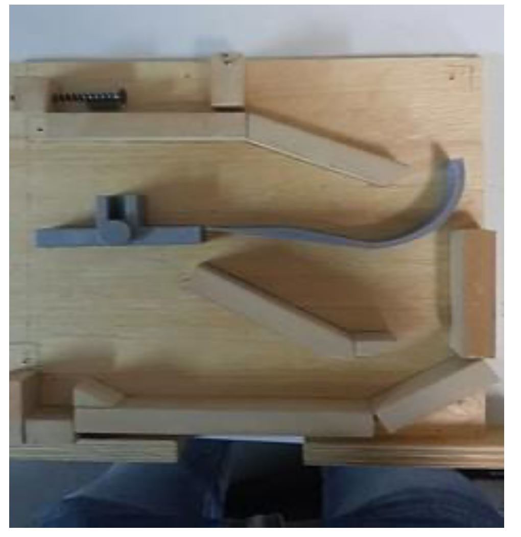
Problems Encountered:
- Over-rotation of the lever arm
- Ball travelled much faster than anticipated
- Ball bouncing on the curved path after impact
- Insufficient kinetic energy for the final slope
Design 1.1 Demonstration
-
Design 1.2 - Problem Resolution
Changes made to counteract Design 1.1 problems:
- Removed initial impact
- Reduced slope height for final horizontal path
- Added stops for the rotating part
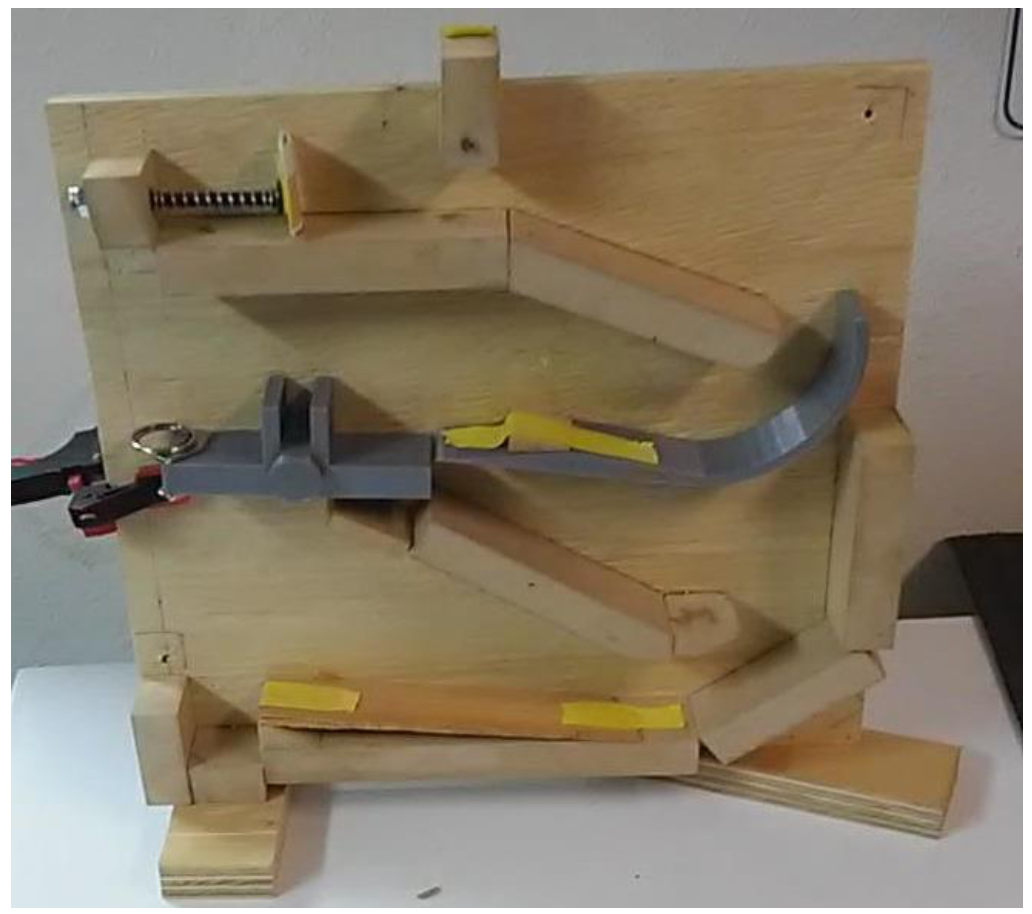
Design 1.2 Demonstration
Result: Ball took 2 seconds (1 second short of objective)
-
Design 1.3 - Final Optimization
Final modifications to achieve 3-5 second objective:
- Added two extra paths to increase total displacement
- Added more gradual slope for constant deceleration
- Placed rotating rod at original position
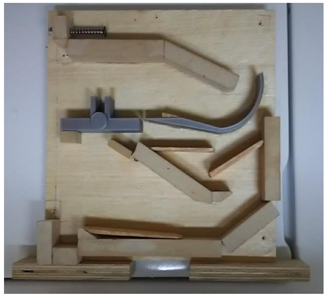
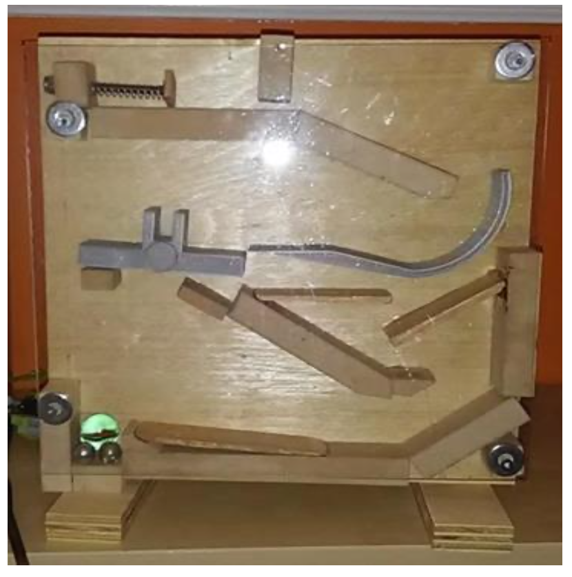
Result: Achieved optimum time of about 3 seconds
Results & Impact
MATLAB Simulation
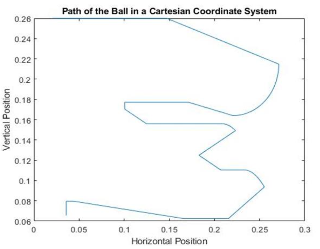
- Successfully achieved 3-5 second travel time objective
- Validated design through MATLAB simulation
- Demonstrated iterative design process and problem-solving
- Documented governing equations and simulation methodology
Lessons Learned
- Importance of iterative design and testing in dynamic systems
- Value of simulation tools (MATLAB) for validation
- Impact of component interactions on overall system performance
- Team collaboration and problem-solving in engineering projects